The sensitivity of the LoRa Technology does not depend on the environment in which it is installed. However the propagation will be much worse underground, due to penetration loss. As a first guess, you could estimate 20 to 30 dB of penetration loss for underground systems.
There is no definite answer to this question as it depends on four dimensions:
- RSSI/SNR of the received packets (simultaneous reception on the same channel)
- Time-on-Air of the packets (equivalent to data rate, the longer the packet, the longer one demodulator of the gateway is used)
- Frequency of the packets (two packets with the same data rate and the same RSSI/SNR will collide unless they are on two different frequencies).
- Number of times per day an end device will send a packet (taking resources another node could use)
ADR can only be used for devices that are permanaently static, this is because the ADR mechanism typically works over a timescale of many hours. This implies that packets could be lost if the end device were to change locations to a higher path-loss environment.
In mobile devices, it is possible to send a mix of different SF packets to allow more frequent information uplinks when closer to a gateway, in a practice known as "Blind ADR".
The network server and application server are software entities that control higher level aspects of a LoRaWAN application. The gateway and end device look after the physical layer connection, the network server looks after the protocol and the application server looks after the application level control and data. All are required.
The maximum bitrate in LoRa is with SF7/bandwdith 500 kHZ and we will be at around 21 kbit/s while HD1080p video bitrate is around 5 Mbit/s in a wire without any handling of packet loss. The LoRaWAN protocol is unfortunately not made for this kind of application.
Let's get the maths going:
One picture with 640 x 480 pixels and 8 bit color code (which is not great) would give you three bytes per pixel (R,G,B color code). This would lead to 921.6 kB of raw data to transmit without any overhead (preamble, header, frame counter,etc). This is a huge amount of data, even at 50 kbit/s, and would take several minutes to send between two devices.
Typically all LoRaWAN makers use 4/5, but strictly speaking the coding rate is not enforced in the LoRaWAN specification. The choice is up to you.
If you are experiencing difficulties with packet reception, then the first question to ask is why?
The answer to this may come in one of two forms - inadequate link budget or such a high sensor deployment density that the probability of packet collision is high. In both cases the best answer is network densification.
In the case of lack of coverage, the addition of a low-cost gateway is the best way of improving your network coverage.
In the case of lack of network capacity, the deployment of an additional gateway to that area will allow other end-nodes in that same area to transition to higher, lower time-on-air data rate - thanks to the ADR mechanism.
With those end devices occupying less transmission time and operating on orthogonal SFs - this will drastically increase your packet success rate - even if your end device setting remain unchanged.
The usually accepted simplification consists of taking into account the Signal to Noise Ratio (SNR) and combining it with RSSI.
- if SNR > 0: packet power = RSSI
- if SNR < 0: packet power = RSSI + SNR
RSSI and SNR expressed in dBm and dB respectively.
DevEUI is a 64-bit number. It is the unique ID of the end-device.
JoinEUI is a 64-bit number. It is the unique ID of the join server, which secures network access and exchanges. In LoRaWAN 1.04, JoinEUI replaced AppEUI
How to get them:
DevEUI key is linked to the end-device, this means end-device manufacturers should contact the IEEE to get a range of unique identifiers.
JoinEUI is provided by the operator of the join server (e.g. network operator, device manufacturer, solution provider). The join server operator should also get a range of unique identifiers from IEEE.
AppKey, aka NwkKey is a 128-bit key which is used to secure the Join-time communication between the source of the message (the end-device) and the destination of the message (the join server). This key is unique for each device and is a shared secret between Join server and device (symmetric cryptography). It is at the heart of the security and must only be known by the device and the join server. AppKey is never sent over the air and must remain secured over the lifetime of the end-device.
How to get it:
AppKey is typically a randomly-generated number that is programmed into the end-device and simultaneously communicated to the join server, so that it can authenticate the messages from the end-device.
The CEPT (European Conference of Postal and Telecommunications Administrations ) is still discussing the harmonization of this band in Europe, but this is not yet completed, so for now we are sticking to the 865-870 MHz frequency band.
There are some technical differences between LoRaWAN and alternative LPWAN technologies which enable a much broader set of applications to be addressed from a bi-directional connectivity, adaptive data rate and end point class perspective, but the key differentiator is the ecosystem, the Certification Program and standardization. If you look at successful technology adoption over the past 10 years all have followed this model. Having different business models, competition, and a diverse ecosystem with industry leaders is the only way to scale volume and deployments. An open standard is also a proven strategy to get acceptance and wide deployment versus proprietary technology, the choice of the various network components; gateways, end-devices, cloud network servers along with chips, development kits and end products from many different suppliers offers a low risk strategy for potential operators or end users.
Last but not least LoRaWAN protects data and privacy like no other LPWAN, it is the most secure solution available in the market with AES 128 encryption on multiple levels for all data from sensor to application server and back.
No, it may marginally pick up, but with no guarantee of successful detection. The bandwidth and spreading factor must be set to the proper value for the Channel Activity Detection (CAD) to work.
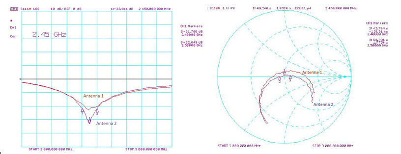
The following data shows the impedance of the two antennas on the SX1280 development kit, with the impedance matching. Here we see in excess of 16 dB of return loss which is good for a portable antenna.
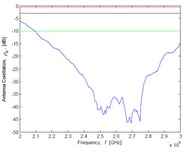
The figure below shows a representation of the antenna system diversity performance, based upon the measured antenna S Parameters. (Based upon the method of Blanch et al). Here the red threshold indicates poor diversity performance, black acceptable diversity performance and green good, i.e. useful, antenna diversity performance.
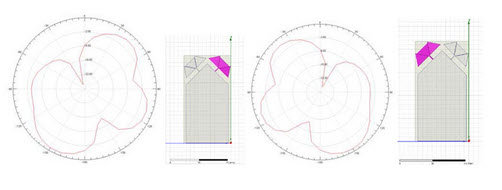
The final plots show the simulated radiation patterns of the two diversity antennas. The pattern corresponding to the highlighted antenna (with the pattern in the same orientation as the board image).
Whilst the ranging performance accuracy is not dependent upon the received signal power (for an example of this and to see how to set up your first ranging measurements, see our application note for more details). It is important to note that the group delay of the transmitter will change depending upon the programmed transmit power.For this reason it is necessary to include a calibration setting for every programmed output power you intend to use in your final application. Our Introduction to Ranging application note gives more information on how to perform the calibration for your design.
The intermediate frequency of the SX1280 in receive mode is 1.625 MHz. This means that the image frequency can be found at twice the IF below the programmed RF centre frequency, i.e. FRF - 3.25 MHz.
The ranging accuracy can be degraded by one of several phenomenon, but we can eparate these into two broad categories: Design and hardware specific errors
- Environmental Errors
- We suggest using the SX1280 Development kit as the hardware for any initial evaluation, this should be updated with the very latest firmware compiled and downloaded from the Tools and SW area. With this configuration complete you should then have all of the design and hardware specific errors correctly calibrated by default. Moreover, the provision of a TCXO on the kit will protect the ranging measurement from temperature based environmental error.The main source of residual error then becomes the radio environement. The radio signal will follow an unpredictable path if there is no direct Line-of-Sight (LoS) between the two units. For this reason, it is necessary to initially evaluate the SX1280 in LOS conditions to ensure that the error is not due to multi-path and reflections specific to a given operating environment.For this reason we have a brief application note which walks you through the first steps of your evaluation that can be found in the Application Notes area of this Knowledge Base.
Recalling that SF11 and SF12 are inaccessible in ranging mode, the highest accuracy ranging setting is to use the highest bandwidth and the highest spreading factor (i.e. 1.6 MHz SF 10). To reduce the time on air of the ranging exchange, one should first decrease the SF then the bandwidth as the latter has the most profound effect on ranging accuracy.